Discuss about "The Schmitt Trigger".
Wednesday, 29 February 2012
Band-Stop Filters
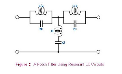
Resonant series and parallel LC circuits may thus be combined to form a notch filter as shown in Figure . In this circuit, the resonant parallel LC circuits are used to block frequencies within the stopband, while the resonant series LC circuit is used to attenuate frequencies within the stopband by shunting them towards the ground.
The following equations apply to the notch filter in Figure 1 above:
1) L = Zo (f2-f1) / (πf1f2); Lf = Zo / (4π(f2-f1))
2) C = 1 / (4π(f2-f1)Zo); Cf = (f2-f1) / (π(f2f1Zo))
3) fo = sqrt(f1f2) = 1 / (2π(sqrt(LC))) = 1 / (2π(sqrt(LfCf)))
4) Zo = sqrt(L/Cf) = sqrt(Lf/C)
where Zo = line impedance; f1 = lower cut-off frequency; f2 = upper cut-off frequency; fo = resonant frequency.
Saturday, 25 February 2012
Band-Pass Filters
Resonant series and parallel LC circuits may thus be combined to form a band-pass filter as shown in Figure. In this circuit, the resonant series LC circuits are used to allow only the desired frequency range to pass while the resonant parallel LC circuit is used to attenuate frequencies outside the passband by shunting them towards the ground.
The following equations apply to the band-pass filter in Figure above:
1) L = Zo / (π(f2-f1)); Lf = (f2-f1) / (4π(f2f1))
2) C = (f2-f1) / (4π(f2f1Zo)); Cf = 1 / (π(f2-f1)Zo)
3) fo = sqrt(f1f2) = 1 / (2π(sqrt(LC))) = 1 / (2π(sqrt(LfCf)))
4) Zo = sqrt(L/Cf) = sqrt(Lf/C)
where Zo = line impedance; f1 = lower cut-off frequency; f2 = upper cut-off frequency; fo = resonant frequency.
Wednesday, 22 February 2012
High-Pass Filters
- Figure shows some common implementations of high-pass filters.
- Note that in each of the high-pass filters shown above, the inductors are in shunt with the input while the capacitors are in series with the input.
- This is because the reactance XL of an inductor increases with the signal frequency, i.e., XL = 2πfL, while the reactance XC of a capacitor decreases with the signal frequency, i.e., XC = 1 / 2πfC.
- Thus in these high-pass filters, the capacitors resist the passing of an ac signal as the frequency decreases, while the inductors shunt them towards the ground as the frequency decreases.
- Either way, the effect is to attenuate the signal as frequency decreases.
The following equations apply to the high-pass filters in Figure above:
1) L = Zo / 4πf
2) C = 1 / (4πf Zo)
3) Zo = sqrt(L/C)
4) f = 1 / (4π sqrt(LC))
where Zo is the line impedance and f is the cut-off frequency of the filter.
Tuesday, 21 February 2012
Subscribe to:
Comments (Atom)


