What is the MOSFET ? Explain about it briefly.
Tuesday, 31 January 2012
Monday, 30 January 2012
Sunday, 29 January 2012
Bipolar Transistor Common-Emitter Output Characteristics
Discuss about the common-emitter configuration of a Bipolar transistor.
Saturday, 28 January 2012
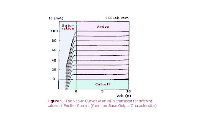
Bipolar Transistor Common-Base Output Characteristics
Discuss about the common-base configuration of a Bipolar transistor.
Friday, 27 January 2012
Zener Diodes
Since a conducting zener diode maintains the voltage across it at a value around its zener voltage, its main purpose is to serve as a voltage regulator. A very simple circuit that demonstrates this is shown in Figure 2. This is a shunt voltage regulator circuit, since the zener diode is connected in shunt (parallel) with the load. In this circuit, Vout will be maintained by the zener diode at the zener voltage level even if Vin changes, as long as Vin exceeds the zener voltage.
If Vin increases, the current flowing through the zener diode ZD1 increases as well, causing the voltage across the resistor R to increase while allowing the voltage across the zener diode to remain at the zener voltage level. Of course, if Vin falls below the zener voltage of ZD1, ZD1 stops conducting, and Vout starts falling with Vin. Note that this circuit is also a very inefficient way to regulate a voltage, since regulation is achieved by shunting current to ground, which is like simply throwing the excess energy away.
Thursday, 26 January 2012
Wednesday, 25 January 2012
Tuesday, 24 January 2012
Monday, 23 January 2012
Sunday, 22 January 2012
p-n junction
Before going to discuss about "Active electronic devices", let us know some thing related to them.
First of all what is p-n junction? Discuss something about it.
First of all what is p-n junction? Discuss something about it.
Friday, 20 January 2012
Note:
Hi guys.....
By today we completed another part. once go through all the topics what we discussed till now. From tomorrow we are going to start the "Active Electronic Devices".
By today we completed another part. once go through all the topics what we discussed till now. From tomorrow we are going to start the "Active Electronic Devices".
Wednesday, 18 January 2012
One more passive electronic device...
Hi friends, one more important passive device is there. can u guess it?
If you think that any device as a passive device, discuss briefly about it.
If you think that any device as a passive device, discuss briefly about it.
Tuesday, 17 January 2012
Monday, 16 January 2012
Inductance
Discuss briefly about the inductance.
How it will vary by varying its connections? describe.
How it will vary by varying its connections? describe.
Happy pongal
Hello friends, ECE wishes u all a very warm pongal greetings...may u have all the prosperity in life and fortune go by ur way......hope u all had a fun filled break until now......it might just be the last holiday for most of us....so do finish it of on a high note....nd get back to work more positively, with more energy and a lot of courage...... wish u all gud luck...
Monday, 9 January 2012
Capacitance
Discuss briefly about the capacitance.
How it will vary by varying its connections? describe.
How it will vary by varying its connections? describe.
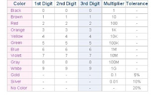
Finding resistance of a resistor.
As shown in Figure 1, a common resistor usually has 4 color bands, the first two of which indicates the first and second digit of its resistance value while the third band indicates the number of zeros that follows the first two digits. The fourth band indicates the error or tolerance of the resistor. For example, the top resistor in Figure has a resistance value of 1 kilo-ohm (10 ohms x 100) +/- 5%. Some resistors have 5 color bands to indicate their resistance values more precisely, an example of which is the bottom resistor of Figure.
Subscribe to:
Comments (Atom)


